Sub-project D4: Wear Simulation
zum 31.12.2008 beendet
Übersicht
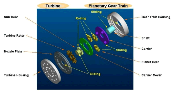
Micromachines, like the SFB 499's demonstrator (micro turbine driving a micro planetary gear train) shown in Fig. 1, promise to revolutionize every product category by enabling the development of smart products. One of the main advantages of such micromachines is their quick response time and high operating frequency due to their extremely low inertia, but this advantage affects negatively on the reliability of these miniaturized machines, in particular they are known to fail prematurely due to excessive wear. Wear is identified as a critical factor, which can limit their life span substantially, and it is compounded by the fact that the surface forces become significant compared to the volume forces at these extremely small dimensions (due to very high surface to volume ratio). Experimental methods, like Pin-on-Disc, Scratch test, Atomic Force
|
Fig. 1: SFB 499's Demonstrator |
Microscopy (AFM) or Surface Force Apparatus (SFA) are not completely sufficient for an exact prediction of the progress of wear and eventually the life span of micromachines. Usually global parameters can be measured with such experiments, while our aim is to develop a software tool that which can compute location and time-dependent wears in tribosystems (implementation of a wear model locally).
Therefore there is a need to develop a finite element based wear simulation tool with a twofold strategy, namely:
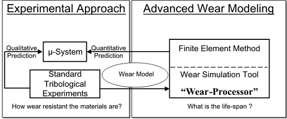
- (i) Identify the wear model by comparing the results from the simulation of wear with the experimental results of, e.g., a pin-on-disc problem (see Fig. 2) and
- (ii) Use this identified wear model to predict wear in real systems with the goal of estimating the life span of a micromachine, such as the SFB 499's demonstrator.
The approach applies to both the macro- and especially the microscales. However, it is of special interest to microscale applications that the high contact pressures and sliding velocities encountered in micromachines would result in high wear rates in the relevant microtribological experiments. And there exists hardly any possibility to improve the finishing of complex-shaped microparts, e.g. microgears, for adjusting the tolerances and the surface quality, which is another reason for the importance of a simulation tool that could predict the influence of the production process and its achievable tolerances on the lifetime of a micromachine.
|
Fig. 2: Wear modeling scheme |
The advantages of having such a wear simulation tool are:
- (i) It can be used to identify a wear model and subsequently the included parameters by simulating microtribology experiments conducted within the parameter space of a certain micromachine.
- (ii) A satisfactorily working wear simulation tool would be able to provide guidelines for material selection and microsystem design.
- (iii) Such a tool will also be able to spell out the requirements on the materials and production technology, so that a given life span can be achieved.
- (iv) The simulation tool can be used to determine the loss of material at the surface and in this way the continuous change of the kinematics, e.g. to consider the microplanetary gear train (SFB 499's demonstrator) for a more realistic stress analysis.
- (v) Hence the life span can be predicted more accurately both by the failure due to kinematics and the breakdown due to drastically increased loads resulting from wear.
With such a wear simulation tool, it is attempted to close the gap between in situ wear measurements, standard tribological experiments and the actual operation of the micromachine.
Due to the complexity of wear and the large number of parameters involved, it is very difficult to predict wear based only on the material properties and the contact information. Therefore our strategy makes use of a simple existing wear model (Archard's Wear Model), which is implemented within a finite element based wear simulation tool. This approach allows for simulating Pin-on-Disc wear experiments and to get a better understanding of the wear process and phenomena. Moreover it has the potential to predict wear for more complex tribosystems with high operation frequencies, as it is the case with micromachines. Our long-term aim is to use the Wear-Processor in an extended form to predict the progress of wear and the life span of a micromachine
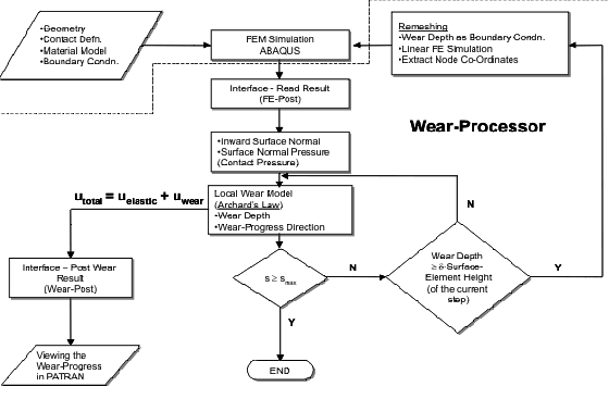
The flow chart for the working of the software tool is shown in Fig. 3.
|
Fig. 3: Flow chart of the Wear-Processor |
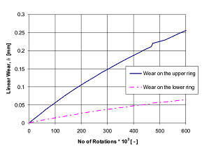
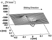
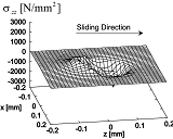
The results from the Wear-Processor for two tribological problems, namely, Ring-on-Ring (loaded hemispherical ring interacting with rotating flat ring) and Pin-on-Disc (loaded hemispherical pin interacting with a revolving disc) are shown in Fig. 4 and Fig. 5 respectively. The progress of wear over the sliding distance (number of rotations/revolutions) on both the interacting surfaces are also shown in the above said figures. It can be seen from Fig. 4c and Fig. 5d that the slope of the wear curve is steadily decreasing, owing to the fact that the severity of wear is decreasing as the contact conforms and so the linear wear per unit sliding distance continuously decreases (running-in). The results from the wear simulation using the Wear-Processor compare favorably with the experimental results available in various literatures. The link to the movies show the progress of wear on both the surfaces as a result of the accompanying decrease in the contact pressure as the contact conforms.
| (a) Ring-on-ring (Axi-symmetric) 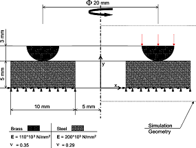
|
(b) Contact pressure distribution in the contact before and after wear 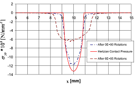
|
(c) Linear wear on the upper and lower ring
 |
(d) Movie: Ring-on-Ring Wear Simulation (15.5 MB) Fig4d-Movie |
|
Fig. 4: Results from the wear simulation using the Wear-Processor in the Ring-on-Ring configuration
|
| (a) Pin-on-disc (3D) 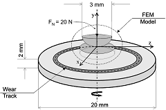
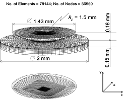
|
(b) Contact pressure in the contact before and after wear 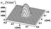 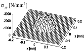
(c) Stress distribution in the direction of sliding before and after wear
|
| (d) Linear wear on the pin and the disc 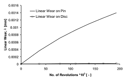
|
(e) Movie: Pin-on-Disc Wear Simulation (3MB) Fig5e-Movie
|
|
Fig. 5: Results from the wear simulation using the Wear-Processor in the pin-on-disc configuration
|
In experimental investigations of wear, the contact pressure computed from the initial configuration (Hertzian peak pressure) is usually used to identify the Archard's wear coefficient, i.e., a global wear model (GWM - In. Max. Pre.) is identified. Usually the wear coefficient is computed at the end of the experiment by fitting the entire sliding range. The geometry, which is specific to a particular tribo-system, is then somehow included in the wear coefficient and also the decay of the contact pressure as the wear progresses is included implicitly in the fit. One of the drawbacks of the global wear model discussed above is that the continuous decrease in the contact pressure is not considered explicitly. However this drawback can be handled by considering a global incremental wear model (GIWM). The term "incremental" means that the contact pressure is updated at different intervals of sliding. The assumptions in this model are:
- (i) Wear takes place only on the pin,
- (ii) The worn out surface is flat,
- (iii) Either an average pressure (load divided by area) or a maximum pressure on the contacting surfaces is considered for the computation of wear, and
- (iv) Frictional effects are not considered.
| (a) Flow chart for the GIWM 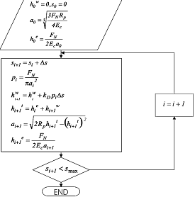
|
(b) Comparison of linear wear over sliding distance using the various global wear models and the Wear-Processor 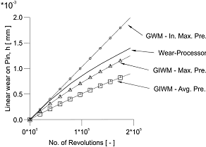
|
|
Fig. 6: Various global wear models |
The computation using the global incremental wear model considering the average pressure (GIWM - Avg. Pre.) is accomplished as shown in Fig. 6a, where p is the contact pressure, FN is the applied normal load, a is the contact radius due to elastic displacement and wear, ht is the total geometry change at the pin tip, Rp is the curvature of the pin, he is the elastic displacement, hw is the current wear depth, kD is the dimensional wear coefficient, s is the interval of the sliding distance, Ec is the elastic modulus of the equivalent surface, smax is the maximum sliding distance, and the subscript i is the current wear increment number. In Fig. 6b, the progress of linear wear on the pin surface obtained from the various wear models is plotted over the number of revolutions (sliding distance). We can see that the global wear model considering the initial maximum pressure is a linear curve with a slope represented by the product of the dimensional wear coefficient and the initial peak pressure. It can be seen from the figures that the results from the wear processor compare favourably with the other global wear models discussed so far. The difference between the curves from the Wear-Processor and the other discussed wear models is due to the fact that the Wear-Processor considers:
- (i) The continuous decay in the contact pressure as the wear on the pin progresses,
- (ii) The effect of friction,
- (iii) The wear on the counter surface.
Even though the global incremental wear models yield a nonlinear curve, the simplifying assumptions made in these models are therefore quite considerable. The computation of the maximum pressure in the contact as 1.5 times higher than the average pressure may only be applicable in the initial stage of sliding when the contact is Hertzian. However, for a large sliding distance we assume that the pressure in the contact should approach a "flattened" distribution and so the GWM - In. Max. Pre. forms the upper limit and the GIWM - Avg. Pre. forms the lower limit for the Wear-Processor.
One of the figures from our article [1] is on the cover of January 2005 issue of the journal Modelling and Simulation in Materials Science and Engineering.
|